115 Vac 115 230 Volt Motor Wiring Diagram

If not the structure won t function as it should be.
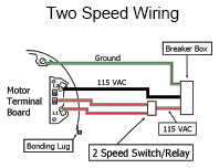
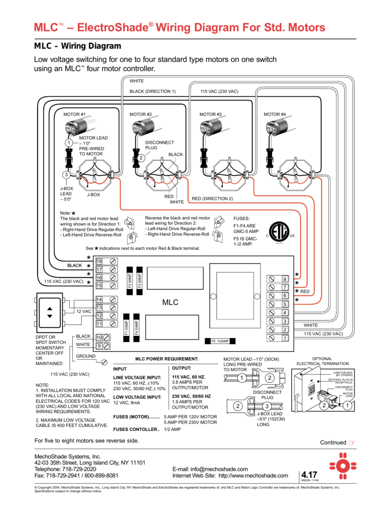
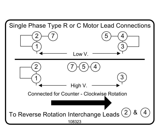
115 vac 115 230 volt motor wiring diagram. 115 230 motor wiring 56cz 88v 50m fix pas gmbh de télécharger le hg 6317 fan diagram besides electric 4dcc131 ge resources century ac zh 4824 schematic on leeson boat lift doerr lr22132 doityourself com community forums yr 8437 with capacitor forward and reverse instant reversing vac or dual stearns rexnord changing voltage sds of single phase motors read more. Move 1 to green to reverse the motor. Thanks for any help. The motor specs are.
In this configuration the motor always starts on 115 but runs on 115 or 230. A three phase motor must be wired based on the diagram on the faceplate. Single phase motor wiring diagram with capacitor baldor single phase motor wiring diagram with capacitor single phase fan motor wiring diagram with capacitor single phase motor connection diagram with capacitor every electrical arrangement is made up of various unique pieces. See photos of wiring diagram and motor nameplate.
The first step is to figure out the voltage of your phases. Each component ought to be placed and linked to different parts in particular manner. Baldor single phase 230v motor wiring diagram collections of dayton electric motors wiring diagram sample. Century ac motor wiring diagram 115 230 volts century ac motor wiring diagram 115 230 volts every electric structure consists of various diverse parts.
This is typically supplied by a battery such as a 9v battery or mains power the outlets in your residence operate at 120v. In the united states for low voltage motors below 600v you can expect either 230v or 460v. Each component ought to be placed and linked to different parts in specific way. The diagram that shows connection for 115 or 230 is missing.
Some motors allow both 120 volt and 240 volt wiring by providing a combination of wires for doing so. Placing the two run windings in parallel. Variety of century ac motor wiring diagram 115 230 volts. Exchange 1 and 2 to reverse the motor.
Residential power is usually in the form of 110 to 120 volts or 220 to 240 volts. That being said there is a wide range of different motors and what you have on hand can be completely different. It shows the parts of the circuit as simplified shapes as well as the power as well as signal connections between the tools. Black to yellow to 1 and red to green to 2.
How to wire a 115 volt electrical outlet. A wiring diagram is a streamlined conventional photographic representation of an electric circuit. Model 5kc43mg40fx 3 4 read more. I have a ge electric motor that can be used on 115 0r 230 volts.
Single phase motors are used to power everything from fans to shop tools to air conditioners. I want to use it on 230 volts. Wiring a motor for 230 volts is the same as wiring for 220 or 240 volts.


